
Demountable Lining System


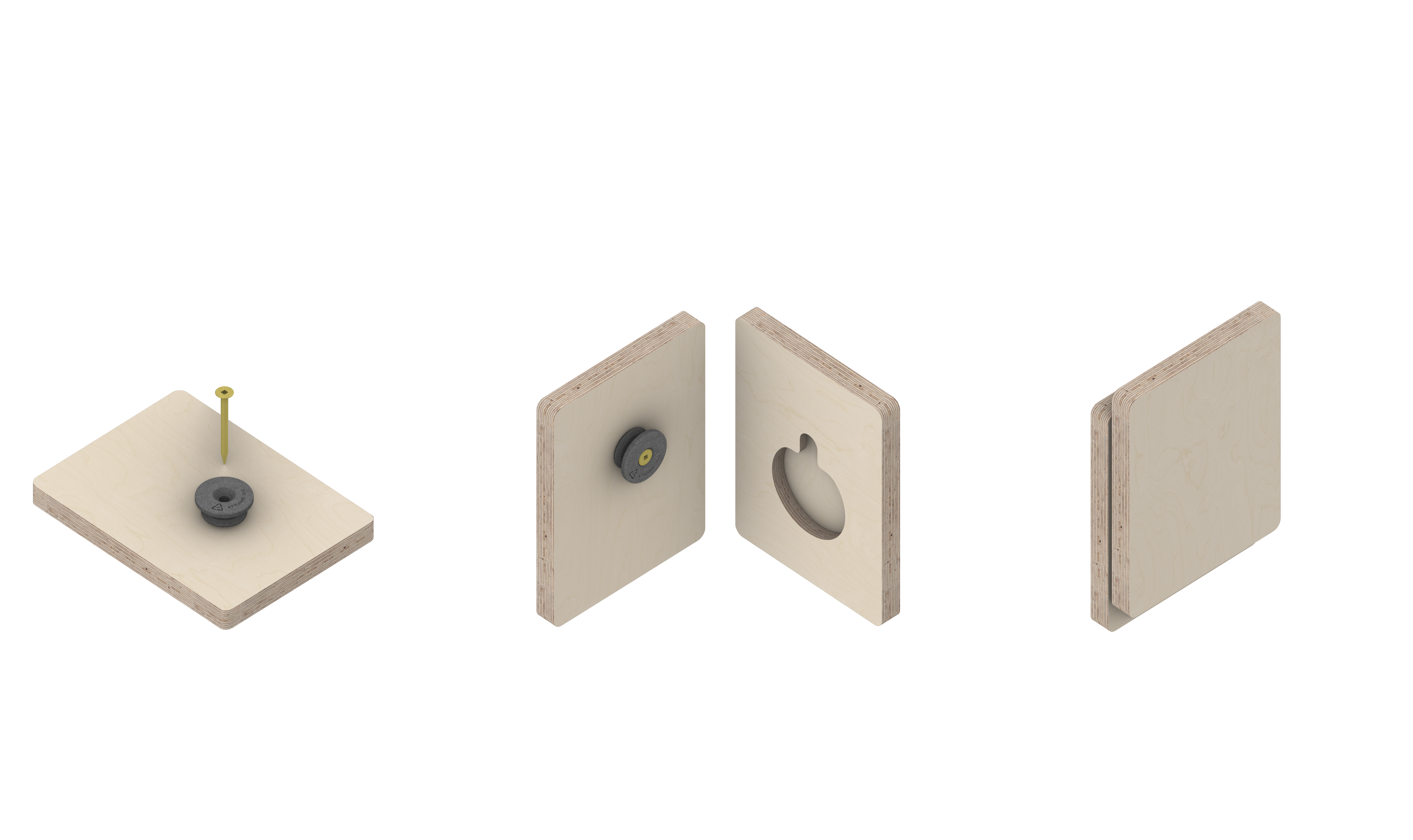
Design: 1-Part (Male) with CNC female - lift-off fixing.
Fixing Method: Screws - one long into frame (typically 40mm 8g CS chip-board screw).
Offset: Flush specification - no gap - lining hard against wall frame. Only works for 16mm or deeper linings.
CAD/CAM Requirements - Lining Side: XF010 CAM Flush Geometry.
CAD/CAM Requirements - Frame Side: A single 3mm dia. pilot hole for clip screw.
Spacing: Max. 600mm centers between clips both horizontally and vertically.
Load Capacity: 30kg per clip.
Usage: For 16mm (5/8 inch) linings. Suitable when the wall thickness needs to be minimised.
Design: 1-Part (Male) with CNC female - lift-off fixing.
Fixing Method: Screws - one long into frame (typically 40mm 8g CS chip-board screw).
Offset: 4mm gap between wall frame and back of linings.
CAD/CAM Requirements - Lining Side: XF010 CAM Typical Geometry.
CAD/CAM Requirements - Frame Side: A single 3mm dia. pilot hole for clip screw.
Spacing: Max. 600mm centers between clips both horizontally and vertically.
Load Capacity: 30kg per clip.
Usage: For any lining 12mm or deeper - allows linings to be easily hung and removed.
Design: 1-Part (Male) with CNC female - lift-off fixing.
Fixing Method: Screws - one long into frame (typically 40mm 8g CS chip-board screw).
Offset: 4mm gap between wall frame and back of linings.
CAD/CAM Requirements - Lining Side: XF010 CAM Rail Geometry.
CAD/CAM Requirements - Frame Side: A single 3mm dia. pilot hole for clip screw.
Spacing: Max. 600mm centers between clips both horizontally and vertically.
Load Capacity: 30kg per clip.
Usage: For any lining 12mm or deeper - allows linings to be easily hung and removed.
Allows linings horozontial location to be adjusted on site via a sliding connection.

